Az áramkör egyszerűen és látványosan bemutatja, miképpen működik a bináris számláló, LED-eken megfigyelhetjük a felfelé számlálás módját. A számlálás sebessége potenciométer segítségével állítható.
Tápfeszültség: 5V DC
Maximum áramfelvétel: 18mA
A készlet forrasztandó alkatrészeket tartalmaz!
1+: 709 Ft 5+: 513 Ft 10+: 483 Ft 20+: 464 Ft 50+: 445 Ft
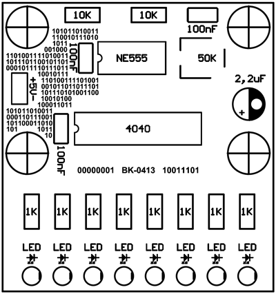
Beültetési ábra
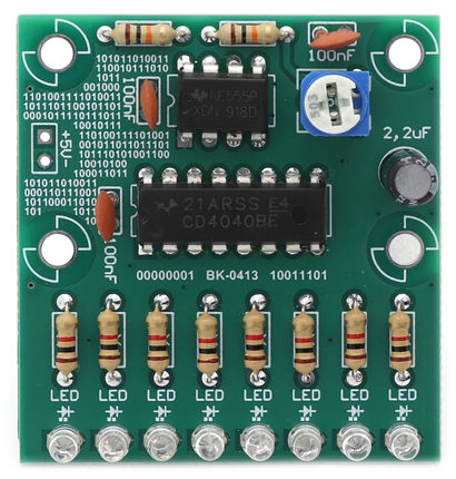
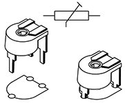
Termékfotó
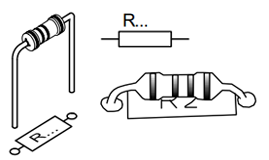
Összeszerelés lépései
1
R1
1K 0.25W
R8
1K 0.25W
R7
1K 0.25W
R6
1K 0.25W
R5
1K 0.25W
R4
1K 0.25W
R3
1K 0.25W
R2
1K 0.25W
R9
10K 0.25W
R10
10K 0.25W
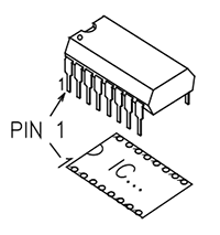
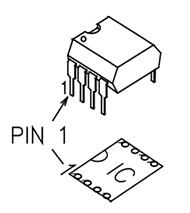
2
U2
CD4040
3
U1
NE555
4
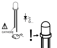
D1
LED
D2
LED
D3
LED
D4
LED
D5
LED
D6
LED
D7
LED
D8
LED
5
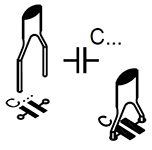
C1
100nF (104)
C2
100nF (104)
C4
100nF (104)
6
P1
50K
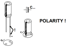
7
C3
2.2uF
Beüzemelés, élesztés
A tápfeszültséget az áramkörön jelölt (+) és (-) pontokra kell csatlakoztatni. A tápellátás polaritását és tényleges feszültségét minden esetben gondosan ellenőrizzük az áramkörre való csatlakoztatás előtt.
(+) = Pozitív tápfeszültség pólus (általában piros)
(-) = Negatív tápfeszültség pólus (általában fekete)
Az 5V tápfeszültség polaritás helyes bekapcsolása után, az áramkör azonnal üzemkész.
Weboldalunk helyes működéséhez sütit készítünk az Ön böngészőjében.
Sütik használatáról bővebben itt olvashat.
A csomagküldés a magyarországi HESTORE raktárból történik.


 Kosár
Kosár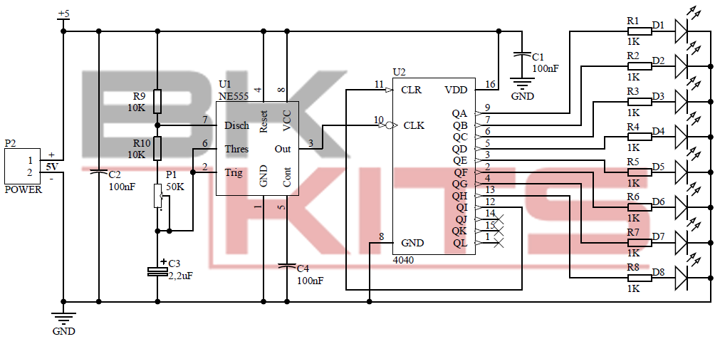

 A csomagküldés a magyarországi HESTORE raktárból történik.